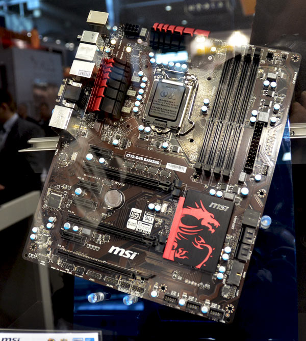

The “V-Check Points” panel located nearby and the enclosed “V-Check cable” set will allow to manually control all the most important system voltages using a voltmeter. There are also three glowing buttons: Power On, Reset and OC Genie, which allows overclocking the system automatically.

There is a row of CPU Phase LEDs in the upper right corner of the board, which shows the number of active phases in the processor voltage regulator circuitry. All heatsinks on this board, including the third one on the chipset, are attached to the PCB with screws. The heating components of the processor voltage regulator circuitry built with high-quality “Military Class III” parts are hidden beneath two additional heatsinks connected via heatpipe. We are going to get back to this matter a little later today when we talk about the mainboard back panel ports and connectors, and you will understand why we specifically stressed this point now. But this time we also didn’t find any brackets for the system case back panel. One of the typical drawbacks of many Micro-Star mainboards is the absence of en external module for the system case front panel with the USB 3.0 ports. As for the actual hardware items, there are few of them included with the board, as you can see from the photograph above. This is a pretty long list mostly due to a variety of documents included with the mainboard. Reliability certificate listing all component testing methods.A poster with overclocking recommendations.A booklet with brief assembly instructions.“V-Check Cable” adapter set for manual voltage monitoring with a voltmeter.“M-Connector” block including modules for easy connection of the system case front panel buttons, indicators and audio.A flexible bridge for 2-way Nvidia SLI graphics configurations.Four Serial ATA cables with metal connector locks, half with L-shaped locks and another half – with straight ones.


 0 kommentar(er)
